spi - SPI API
Quickstart
Example: communication with a SPI data flash (half-duplex example)
# Instantiate a SPI controller
spi = SpiController()

# Configure the first interface (IF/1) of the FTDI device as a SPI master
spi.configure('ftdi://ftdi:2232h/1')

# Get a port to a SPI slave w/ /CS on A*BUS3 and SPI mode 0 @ 12MHz
slave = spi.get_port(cs=0, freq=12E6, mode=0)

# Request the JEDEC ID from the SPI slave
jedec_id = slave.exchange([0x9f], 3)
Example: communication with a remote SPI device using full-duplex mode
# Instantiate a SPI controller
# We need want to use A*BUS4 for /CS, so at least 2 /CS lines should be
# reserved for SPI, the remaining IO are available as GPIOs.
spi = SpiController(cs_count=2)

# Configure the first interface (IF/1) of the FTDI device as a SPI master
spi.configure('ftdi://ftdi:2232h/1')

# Get a port to a SPI slave w/ /CS on A*BUS4 and SPI mode 2 @ 10MHz
slave = spi.get_port(cs=1, freq=10E6, mode=2)

# Synchronous exchange with the remote SPI slave
write_buf = b'\x01\x02\x03'
read_buf = slave.exchange(write_buf, duplex=True)
Example: communication with a SPI device and an extra GPIO
# Instantiate a SPI controller
spi = SpiController()

# Configure the first interface (IF/1) of the first FTDI device as a
# SPI master
spi.configure('ftdi://::/1')

# Get a SPI port to a SPI slave w/ /CS on A*BUS3 and SPI mode 0 @ 12MHz
slave = spi.get_port(cs=0, freq=12E6, mode=0)

# Get GPIO port to manage extra pins, use A*BUS4 as GPO, A*BUS5 as GPI
gpio = spi.get_gpio()
gpio.set_direction(pins=0b0011_0000, direction=0b0001_0000)

# Assert GPO pin
gpio.write(0x10)
# Write to SPI slace
slave.write(b'hello world!')
# Release GPO pin
gpio.write(0x00)
# Test GPI pin
pin = bool(gpio.read() & 0x20)
Example: managing non-byte aligned transfers
# Instantiate a SPI controller
spi = SpiController()

# Configure the first interface (IF/1) of the first FTDI device as a
# SPI master
spi.configure('ftdi://::/1')

# Get a SPI port to a SPI slave w/ /CS on A*BUS3
slave = spi.get_port(cs=0)

# write 6 first bits of a byte buffer
slave.write(b'\xff', droptail=2)

# read only 13 bits from a slave (13 clock cycles)
# only the 5 MSBs of the last byte are valid, 3 LSBs are force to zero
slave.read(2, droptail=3)
See also pyspiflash module and tests/spi.py, which provide more detailed
examples on how to use the SPI API.
Classes
- class pyftdi.spi.SpiPort(controller, cs, cs_hold=3, spi_mode=0)
SPI port
An SPI port is never instanciated directly: use
SpiController.get_port()method to obtain an SPI port.Example:
>>> ctrl = SpiController()
>>> ctrl.configure('ftdi://ftdi:232h/1')
>>> spi = ctrl.get_port(1)
>>> spi.set_frequency(1000000)
>>> # send 2 bytes
>>> spi.exchange([0x12, 0x34])
>>> # send 2 bytes, then receive 2 bytes
>>> out = spi.exchange([0x12, 0x34], 2)
>>> # send 2 bytes, then receive 4 bytes, manage the transaction
>>> out = spi.exchange([0x12, 0x34], 2, True, False)
>>> out.extend(spi.exchange([], 2, False, True))
- property cs: int
Return the /CS index.
- Returns:
the /CS index (starting from 0)
- exchange(out=b'', readlen=0, start=True, stop=True, duplex=False, droptail=0)
Perform an exchange or a transaction with the SPI slave
- Parameters:
out (
Union[bytes,bytearray,Iterable[int]]) – data to send to the SPI slave, may be empty to read out data from the slave with no write.readlen (
int) – count of bytes to read out from the slave, may be zero to only write to the slavestart (
bool) – whether to start an SPI transaction, i.e. activate the /CS line for the slave. Use False to resume a previously started transactionstop (
bool) – whether to desactivete the /CS line for the slave. Use False if the transaction should complete with a further call to exchange()duplex (
bool) – perform a full-duplex exchange (vs. half-duplex), i.e. bits are clocked in and out at once.droptail (
int) – ignore up to 7 last bits (for non-byte sized SPI accesses)
- Return type:
bytes- Returns:
an array of bytes containing the data read out from the slave
- flush()
Force the flush of the HW FIFOs
- Return type:
None
- force_select(level=None, cs_hold=0)
Force-drive /CS signal.
This API is not designed for a regular usage, but is reserved to very specific slave devices that require non-standard SPI signalling. There are very few use cases where this API is required.
- Parameters:
level (
Optional[bool]) – level to force on /CS output. This is a tri-state value. A boolean value forces the selected signal level; note that SpiPort no longer enforces that following API calls generates valid SPI signalling: use with extreme care. None triggers a pulse on /CS output, i.e. /CS is not asserted once the method returns, whatever the actual /CS level when this API is called.cs_hold (
float) – /CS hold duration, as a unitless value. It is not possible to control the exact duration of the pulse, as it depends on the USB bus and the FTDI frequency.
- Return type:
None
- property frequency: float
Return the current SPI bus block
- property mode: int
Return the current SPI mode.
- Returns:
the SPI mode
- read(readlen=0, start=True, stop=True, droptail=0)
Read out bytes from the slave
- Parameters:
readlen (
int) – count of bytes to read out from the slave, may be zero to only write to the slavestart (
bool) – whether to start an SPI transaction, i.e. activate the /CS line for the slave. Use False to resume a previously started transactionstop (
bool) – whether to desactivete the /CS line for the slave. Use False if the transaction should complete with a further call to exchange()droptail (
int) – ignore up to 7 last bits (for non-byte sized SPI accesses)
- Return type:
bytes- Returns:
an array of bytes containing the data read out from the slave
- set_frequency(frequency)
Change SPI bus frequency
- Parameters:
frequency (
float) – the new frequency in Hz
- set_mode(mode, cs_hold=None)
Set or change the SPI mode to communicate with the SPI slave.
- Parameters:
mode (
int) – new SPI modecs_hold (
Optional[int]) – change the /CS hold duration (or keep using previous value)
- Return type:
None
- write(out, start=True, stop=True, droptail=0)
Write bytes to the slave
- Parameters:
out (
Union[bytes,bytearray,Iterable[int]]) – data to send to the SPI slave, may be empty to read out data from the slave with no write.start (
bool) – whether to start an SPI transaction, i.e. activate the /CS line for the slave. Use False to resume a previously started transactionstop (
bool) – whether to desactivete the /CS line for the slave. Use False if the transaction should complete with a further call to exchange()droptail (
int) – ignore up to 7 last bits (for non-byte sized SPI accesses)
- Return type:
None
- class pyftdi.spi.SpiGpioPort(controller)
GPIO port
A SpiGpioPort instance enables to drive GPIOs wich are not reserved for SPI feature as regular GPIOs.
GPIO are managed as a bitfield. The LSBs are reserved for the SPI feature, which means that the lowest pin that can be used as a GPIO is b4:
b0: SPI SCLK
b1: SPI MOSI
b2: SPI MISO
b3: SPI CS0
b4: SPI CS1 or first GPIO
If more than one SPI device is used, less GPIO pins are available, see the cs_count argument of the SpiController constructor.
There is no offset bias in GPIO bit position, i.e. the first available GPIO can be reached from as
0x10.Bitfield size depends on the FTDI device: 4432H series use 8-bit GPIO ports, while 232H and 2232H series use wide 16-bit ports.
An SpiGpio port is never instanciated directly: use
SpiController.get_gpio()method to obtain the GPIO port.- property all_pins: int
Report the addressable GPIOs as a bitfield.
A true bit represents a pin which may be used as a GPIO, a false bit a reserved pin (for SPI support)
- Returns:
the bitfield of configurable GPIO pins.
- property direction: int
Provide the FTDI GPIO direction.self
A true bit represents an output GPIO, a false bit an input GPIO.
- Returns:
the bitfield of direction.
- property pins: int
Report the configured GPIOs as a bitfield.
A true bit represents a GPIO, a false bit a reserved or not configured pin.
- Returns:
the bitfield of configured GPIO pins.
- read(with_output=False)
Read GPIO port.
- Parameters:
with_output (
bool) – set to unmask output pins- Return type:
int- Returns:
the GPIO port pins as a bitfield
- set_direction(pins, direction)
Change the direction of the GPIO pins.
- Parameters:
pins (
int) – which GPIO pins should be reconfigureddirection (
int) – direction bitfield (high level for output)
- Return type:
None
- property width: int
Report the FTDI count of addressable pins.
Note that all pins, including reserved SPI ones, are reported.
- Returns:
the count of IO pins (including SPI ones).
- write(value)
Write GPIO port.
- Parameters:
value (
int) – the GPIO port pins as a bitfield- Return type:
None
- class pyftdi.spi.SpiController(cs_count=1, turbo=True)
SPI master.
- Parameters:
cs_count (
int) – is the number of /CS lines (one per device to drive on the SPI bus)turbo (
bool) – increase throughput over USB bus, but may not be supported with some specific slaves
- property active_channels: Set[int]
Provide the set of configured slaves /CS.
- Returns:
Set of /CS, one for each configured slaves
- property channels: int
Provide the maximum count of slaves.
- Returns:
the count of pins reserved to drive the /CS signal
- close(freeze=False)
Close the FTDI interface.
- Parameters:
freeze (
bool) – if set, FTDI port is not reset to its default state on close.- Return type:
None
- configure(url, **kwargs)
Configure the FTDI interface as a SPI master
- Parameters:
url (
Union[str,Device]) – FTDI URL string, such asftdi://ftdi:232h/1kwargs (
Mapping[str,Any]) – options to configure the SPI bus
- Return type:
None
Accepted options:
interface: when URL is specifed as a USB device, the interface named argument can be used to select a specific port of the FTDI device, as an integer starting from 1.directiona bitfield specifying the FTDI GPIO direction, where high level defines an output, and low level defines an input. Only useful to setup default IOs at start up, useSpiGpioPortto drive GPIOs. Note that pins reserved for SPI feature take precedence over any this setting.initiala bitfield specifying the initial output value. Only useful to setup default IOs at start up, useSpiGpioPortto drive GPIOs.frequencythe SPI bus frequency in Hz. Note that each slave may reconfigure the SPI bus with a specialized frequency.cs_countcount of chip select signals dedicated to select SPI slave devices, starting from A*BUS3 pinturbowhether to enable or disable turbo modedebugto increase log verbosity, using MPSSE tracer
- property configured: bool
Test whether the device has been properly configured.
- Returns:
True if configured
- property direction
Provide the FTDI pin direction
A true bit represents an output pin, a false bit an input pin.
- Returns:
the bitfield of direction.
- exchange(frequency, out, readlen, cs_prolog=None, cs_epilog=None, cpol=False, cpha=False, duplex=False, droptail=0)
Perform an exchange or a transaction with the SPI slave
- Parameters:
out (
Union[bytes,bytearray,Iterable[int]]) – data to send to the SPI slave, may be empty to read out data from the slave with no write.readlen (
int) – count of bytes to read out from the slave, may be zero to only write to the slave,cs_prolog (
Optional[bytes]) – the prolog MPSSE command sequence to execute before the actual exchange.cs_epilog (
Optional[bytes]) – the epilog MPSSE command sequence to execute after the actual exchange.cpol (
bool) – SPI clock polarity, derived from the SPI modecpol – SPI clock phase, derived from the SPI mode
duplex (
bool) – perform a full-duplex exchange (vs. half-duplex), i.e. bits are clocked in and out at once or in a write-then-read manner.droptail (
int) – ignore up to 7 last bits (for non-byte sized SPI accesses)
- Return type:
bytes- Returns:
bytes containing the data read out from the slave, if any
- flush()
Flush the HW FIFOs.
- Return type:
None
- force_control(frequency, sequence)
Execution an arbitrary SPI control bit sequence. Use with extreme care, as it may lead to unexpected results. Regular usage of SPI does not require to invoke this API.
- Parameters:
sequence (
bytes) – the bit sequence to execute.- Return type:
None
- property frequency: float
Provides the current SPI clock frequency in Hz.
- Returns:
the SPI bus clock frequency
- property frequency_max: float
Provides the maximum SPI clock frequency in Hz.
- Returns:
SPI bus clock frequency
- get_gpio()
Retrieve the GPIO port.
- Return type:
- Returns:
GPIO port
- get_port(cs, freq=None, mode=0)
Obtain a SPI port to drive a SPI device selected by Chip Select.
- Note:
SPI mode 1 and 3 are not officially supported.
- Parameters:
cs (
int) – chip select slot, starting from 0freq (
Optional[float]) – SPI bus frequency for this slave in Hzmode (
int) – SPI mode [0, 1, 2, 3]
- Return type:
- property gpio_all_pins
Report the addressable GPIOs as a bitfield.
A true bit represents a pin which may be used as a GPIO, a false bit a reserved pin (for SPI support)
- Returns:
the bitfield of configurable GPIO pins.
- property gpio_pins
Report the configured GPIOs as a bitfield.
A true bit represents a GPIO, a false bit a reserved or not configured pin.
- Returns:
the bitfield of configured GPIO pins.
- property is_inverted_cpha_supported: bool
Report whether it is possible to supported CPHA=1.
- Returns:
inverted CPHA supported (with a kludge)
- read_gpio(with_output=False)
Read GPIO port
- Parameters:
with_output (
bool) – set to unmask output pins- Return type:
int- Returns:
the GPIO port pins as a bitfield
- set_gpio_direction(pins, direction)
Change the direction of the GPIO pins
- Parameters:
pins (
int) – which GPIO pins should be reconfigureddirection (
int) – direction bitfield (on for output)
- Return type:
None
- terminate()
Close the FTDI interface.
- Note:
deprecated API, use close()
- Return type:
None
- property width
Report the FTDI count of addressable pins.
- Returns:
the count of IO pins (including SPI ones).
- write_gpio(value)
Write GPIO port
- Parameters:
value (
int) – the GPIO port pins as a bitfield- Return type:
None
Exceptions
- exception pyftdi.spi.SpiIOError
SPI I/O error
GPIOs
See GPIOs for details
Tests
- SPI sample tests expect:
MX25L1606E device on /CS 0, SPI mode 0
ADXL345 device on /CS 1, SPI mode 2
RFDA2125 device on /CS 2, SPI mode 0
Checkout a fresh copy from PyFtdi github repository.
See FTDI device pinout for FTDI wiring.
# optional: specify an alternative FTDI device
export FTDI_DEVICE=ftdi://ftdi:2232h/1
# optional: increase log level
export FTDI_LOGLEVEL=DEBUG
# be sure to connect the appropriate SPI slaves to the FTDI SPI bus and run
PYTHONPATH=. python3 pyftdi/tests/spi.py
Limitations
SPI Modes 1 & 3
FTDI hardware does not support cpha=1 (mode 1 and mode 3). As stated in Application Node 114:
“It is recommended that designers review the SPI Slave data sheet to determine the SPI mode implementation. FTDI device can only support mode 0 and mode 2 due to the limitation of MPSSE engine.”.
Support for mode 1 and mode 3 is implemented with some workarounds, but generated signals may not be reliable: YMMV. It is only available with -H series (FT232H, FT2232H, FT4232H/HA/HP).
The 3-clock phase mode which has initially be designed to cope with I2C signalling is used to delay the data lines from the clock signals. A direct consequence of this workaround is that SCLK duty cycle is not longer 50% but 25% (mode 1) or 75% (mode 3). Again, support for mode 1 and mode 3 should be considered as a kludge, you’ve been warned.
Time-sensitive usage
Due to the MPSSE engine limitation, it is not possible to achieve time-controlled request sequence. In other words, if the SPI slave needs to receive command sequences at precise instants - for example ADC or DAC devices - PyFtdi use is not recommended. This limitation is likely to apply to any library that relies on FTDI device. The USB bus latency and the lack of timestamped commands always add jitter and delays, with no easy known workaround.
Wiring
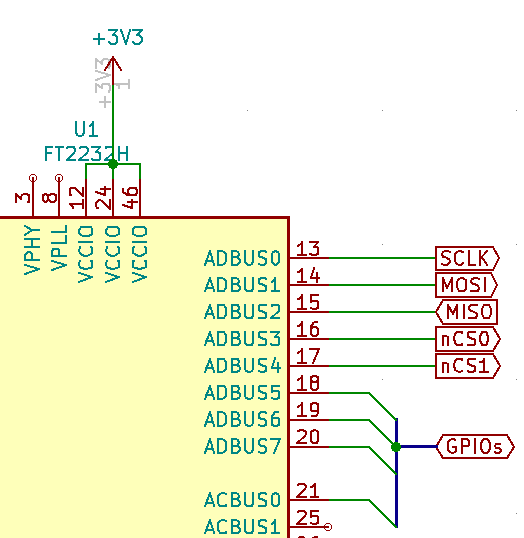
Fig.1: FT2232H with two SPI slaves
AD0should be connected to SCLKAD1should be connected to MOSIAD2should be connected to MISOAD3should be connected to the first slave /CS.AD4should be connected to the second slave /CS, if anyremaining pins can be freely used as regular GPIOs.
Fig.1:
AD4may be used as a regular GPIO if a single SPI slave is usedAD5may be used as another /CS signal for a third slave, in this case the first available GPIO isAD6, etc.